Determining
the capture window of a capture card
Arachnotron, December 2th 2003
Introduction
I am assuming the reader is familiar with the concept of video lines,
resolution, aspect ratio and active picture area. If not, look at the
sites mentioned in the references.
One assumption often made in video capture documentation is that
capturing equipment captures exactly the theoretical active area of a
video line,
i.e. 52 microseconds (= µs) for PAL and 52.66 µs for NTSC.
When you capture,
the picture information in this area is sampled and distributed over
the
number of pixels chosen by you when you set the horizontal resolution
in the
capture program. The higher the horizontal resolution you choose, the
smaller the amount of time such a pixel represents.(PLAATJE HIER ???) If
you were to make
captures at 480x480 and 720x480 and compare them on your computer
screen, both would depict the same part of the TV picture but the
720x480 version would look more stretched horizontally.
Basically, all cards have a single sampling rate and generate all other
resolutions by resizing.
Unfortunately, the capture area used by a device is programmed by the
driver and often manufacturers will set active area's which are either
shorter or longer then the theoretical active area. And of
course, they
never tell you what it is. Even when dealing with the same capture
device, for instance a BT878, different drivers can use different
capture area's. In principle it is even possible that a manufacturer
decides to change the capture window when it releases a new driver
version.
The result of this is that when you capture at the same resolution
using different devices or drivers, the results might not look the
same. The
capture made with the device with the shortest capture window will look
stretched out horizontally compared to a capture made on the device
with the longer capture window.
The capture window influences the aspect ratio of the picture. If
you want the aspect ratio to be correct on playback, you have to
correct for this. This page aims to give simple instructions on how to
determine what capture window your card uses utilizing standard DVD
player as a signal source. Look in the Doom9 TV capture Guide
for more information on what to do once you know what it is.
Using the DVD signal as a reference
A DVD player operates at 13.5 MHz. In other words, it plays back
13000000 pixels in a second. This means that a single pixel in your
MPEG2 file is played back in exactly
1/13000000= 0.07407 µs or 74.07 ns. More information about the
way a DVD player plays back a MPEG2 file can be found here.
Note that this relationship is only
valid for a standard stand-alone DVD player. A multimedia-PC will do
some scaling of it's own when generating a TV picture and is unsuitable
as a reference for determining the capture window!
To calibrate your capture device, simply connect your DVD player to
your capture device. If possible, use an Y/C or S-video cable to do
this, but a composite video cable will do if neccesary.
Now play a DVD disk, capture a small clip en see how many of the
original DVD pixels made it into your capture file.
divide the number of DVD pixels by 13.5 and presto, you have your
capture window in µs. For example, 720 DVD pixels equal
720/13.5 = 53.33 µs.
Unfortunately, this is not as easy as it sounds. You would need to rip
the DVD and try to extract a single frame which is also present in the
captured file to be able to compare the two. Also, because of the way
color is handled by both DVD's and capture devices ( color information
is shared by two pixels, making the resolution for color half of that
for black and white) colored pixels can make it extremely difficult to
see exactly
where the capture ends.
To help with this I created a test DVD for both PAL and NTSC. You can
download them in the download
area. You need RAR to unpack
the files. They contain a ready made VIDEO_TS folder which can be
burned to video-DVD using Nero burning Rom or any other DVD burning
program. If you don't own a DVD burner, a S-VCD iso-image can be found below for use with a CD burner
though the results will be slightly less accurate.
The test DVD contains a 10 s clip in which a single frame is repeated.
The DVD is set to play in a loop. Below you can see the NTSC version of
the test frame. Click it to see it full-size. To be able to analyze the
results with one-pixel accuracy it is black and white. To further
optimize it it contains only white pixels on a 50% gray background. Why
this is a good idea is told here

(Uitleg wat je aan de randen ziet, horizontale lijn)
(Plaatje lijn linker 20 DVD pixels, daar onder resulterende
analogue signal ; black level, up naar white, down naar grey, met
sample frame er onder en daar weer onder de resulterende pixels)
Using a SVCD as a
reference
Many DVD players will also play S-VCD's. A S-VCD pixel is
played
back at a lower rate than DVD's, 9 MHz. This means that a single
pixel is played back in exactly 1/9000000 =0.1111 µs or
111.1 ns. Because of this S-VCD pixels are 50% wider than DVD
pixels and the results will be slightly less accurate. Apart from that
the method works just the same as for a DVD, only now you divide
by 9 instead of 13.5.
For example 480 S-VCD pixels equal 480 / 9 = 53.33 µs.
Capturing and how to interpret your results
The following picture demonstrates the relation between the original
pixels in line 130 of the mpeg file on the DVD and the final pixels in
your capture file. The vertical lines are 74.07 ns apart.
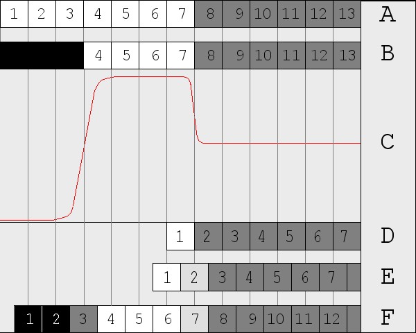
- A. line 130 of the
720x480 mpeg file. Pixels 1-7 are white, the following ones are 50% gray
- B. On playback, the DVD
player crops the first 3 pixles and replaces them with horizontal
blanking.
- C. The analogue signal
produced by the DVD player. The signal rises from blanking level
to white level, stays at white level for about 0.2 µs and
drops down again to 50% grey level. Note the rise time going from
blanking level to white level (rise time is the time it takes to go
from 10% to 90% of maximum signal). This is almost 0.06 µs which
equals 0.8 DVD pixel! This is why a vertical change from black to white
on a DVD will always result in a grey pixel in the capture. To increase
the precision, the test DVD uses white lines on a 50% grey background,
since going from white level to 50% grey takes less time.
- D. Theoretical
capture card with the capture window coinciding with the signal
resulting from DVD pixel 7.
- E. Theoretical capture
card with the sampling grid 'out of phase' with the pixelgrid on the
DVD. The first pixel captured contains signal from DVD pixels 6 and 7,
and is white, but capture pixel 2 contains signal from the flank and
results in a grey color between white and 50% grey.
- F. Theoretical capture
card with the capturing window beginning before the start of the active
part of the DVD signal. Because of this, two black pixels are captured
on the left. The third pixel is grey, since most of the analogue signal
in this area is on a slope between black and white.
Some examples
De getallen uit mijn Post + erratic, of een selectie daar uit in een
tabel
A special case: BT878 based capture cards
stukje over uitlezen registers BT878, link naar Trevlac
References